


Choosing a shielding gas for MAG welding: what the CO₂ ratio changes
The CO₂ ratio in an argon–carbon dioxide mixture directly changes penetration, spatter and bead appearance. Here is how DIN EN ISO 14175 classes work and which mixture suits which job.
4 min read
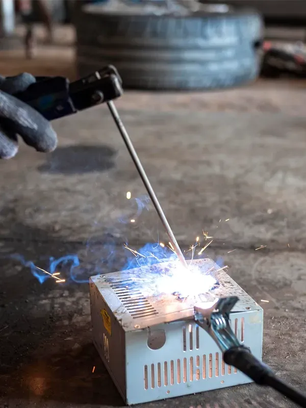
Weld quality is usually credited to the wire and the current settings. Yet the shielding gas matters just as much: with the same wire, the same machine and the same welder, changing only the gas mixture visibly changes penetration, spatter and the amount of post-weld cleaning work.
This article explains how argon–carbon dioxide mixtures for MAG welding are classified, what the CO₂ ratio changes in practice, and which mixture is preferred for which job.
What does a shielding gas actually do?
A shielding gas does more than “keep the air away”. It performs several jobs at once in the arc region:
- It protects the molten pool. Oxygen and nitrogen in the air react with liquid metal and cause porosity and brittleness.
- It stabilises the arc. The ionisation behaviour of the gas determines arc voltage and stability.
- It carries heat. Thermal conductivity shapes the width of the pool and the penetration profile.
- It governs droplet transfer. Whether you can work in short arc or spray arc depends largely on the mixture.
How to read DIN EN ISO 14175
DIN EN ISO 14175 classifies shielding gases into lettered groups. Once you see this code on a data sheet, you can tell what a mixture is for without knowing the brand name:
| Group | Content | Typical use |
|---|---|---|
| I | Inert gases — argon, helium | TIG welding, MIG welding of aluminium and copper |
| M1 / M2 / M3 | Oxidising mixtures — Ar + CO₂ and/or O₂ | MAG welding; oxidising strength rises from M1 to M3 |
| C | Carbon dioxide based — C1 = 100% CO₂ | Thick sections where deep penetration is required |
| R | Reducing — Ar + H₂ | Root shielding and TIG on stainless steel |
For example, the data sheet for Corgon 18 states group M21 (ArC) and the mixture is 82% argon + 18% carbon dioxide — an oxidising MAG gas with a mid-range CO₂ content.
What the CO₂ ratio changes in practice
As carbon dioxide increases, the arc becomes “harder”: penetration deepens and heat input rises, but so do spatter and oxidation. As argon increases the opposite happens — the bead is cleaner and smoother with less spatter, while penetration stays finger-shaped and shallower.
| CO₂ ratio | Arc and bead | Where it works |
|---|---|---|
| 5% – 12% | Soft arc, very little spatter, smooth bead appearance | Thin sheet, visible welds, robotic welding, spray arc |
| 15% – 20% | Balanced: reasonable penetration, acceptable spatter | General fabrication, medium-thickness structural steel |
| 20% – 25% | Deep penetration, tolerant of gaps and mill scale | Thick sections, site welding, imperfect joint preparation |
| 100% (C1) | Deepest penetration, highest spatter | Thick sections where speed and penetration come first |
Which mixture for which job?
The Corgon family consists of argon–carbon dioxide mixtures at different ratios. A few of the data sheets in our guide:
- Corgon 8 — low CO₂; thin sheet and work where bead appearance matters.
- Corgon 12 — a balance between low spatter and reasonable penetration.
- Corgon 18 — the most common mixture in general fabrication; short arc and spray arc alike.
- Corgon 20 — when penetration comes first and there is room for post-weld cleaning.
- Pure Carbon Dioxide — deep penetration on thick sections where spatter is acceptable.
Stainless and high-alloy steels use mixtures developed specifically for those materials rather than argon–carbon dioxide; you can find data sheets for the Cronigon and Varigon families in our gas guide.
Choosing the gas is not enough: application notes
- Flow rate. Too low and the pool is unprotected; too high and turbulence draws air in. Rates of 12–18 l/min are common in practice; the exact figure follows the torch, the position and the welding procedure (WPS).
- Draughts. Wind disperses the gas shield on site. Use a screen or adjust the flow accordingly.
- Leaks. Worn hoses and loose fittings dilute the gas — a frequent but late-detected cause of porosity.
- Nozzle cleanliness. A nozzle clogged with spatter disturbs the gas flow — a low-CO₂ mixture also reduces this maintenance load.
- Torch angle. An excessive push or drag angle lets air under the gas shield.
In short
The CO₂ ratio sets the balance between penetration and cleaning labour. Low CO₂ makes sense for thin sheet and visible welds, high CO₂ for thick sections and site work, and most general fabrication settles around 18%. Tell us your material, thickness and welding position and we will determine the right mixture and cylinder size together.
More technical articles
-
Modified atmosphere packaging (MAP): how gas extends shelf life
What nitrogen, carbon dioxide and oxygen do inside the pack, typical atmospheres by product group, and what “food grade gas” actually means.
-
Gas cylinder colour codes and safe handling: an EN 1089-3 guide
What the shoulder colour tells you, which gas carries which colour, and the rules that apply in storage. EN 1089-3 colour coding plus practical safety notes.
-
What is argon and where is it used? Purity grades and safety
Argon’s properties, how it is produced, what purity grades from 4.6 to 6.0 mean, applications from welding to electronics, and the risk it carries as an asphyxiant.